In the IT industry for the past couple of years is the term IoT, which stands for Internet of Things. IoT refers to all of the things that are, well, connected to the Internet, and that’s how it got its name. However, IoT isn’t really a new concept, we’ve been connecting devices to the Internet. IoT is more than the collection of data-using sensors. More specifically, IoT involves the processing of the data collected to derive useful information and support better decision-making (see Figure 1). For example, in some countries, rain gauges have been installed to measure the amount of rainfall throughout the year, and the data collected have been analyzed and used to better manage flash floods.
Besides data collection and data analysis, the ability to act on the data collected instantly is also an important criterion in deciding if a system is an IoT system. If the data gathered by rain gauges installed in drains in the previous example indicated that a particular drain has an unusually high level, the maintenance crew is alerted and dispatched immediately to monitor and address the situation.
IoT and Maker Movement
Another factor driving the momentous adoption of the IoT system is the rise of the maker culture. The maker culture encourages hobbyists (and professionals alike) to create their own devices as well as tinker with existing ones to find solutions to solve their specific problems.
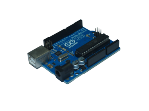
With the maker movement comes a host of DIY electronic platforms, such as Arduino and Raspberry Pi. Arduino (seeFigure 2) is a small and inexpensive electronic board that allows you to connect to various external accessories (such as sensors) and create applications to use the data collected.
Figure 2: The Arduino UNO boardAnother open-source hardware platform that has gotten very popular with hobbyists these days is Raspberry Pi. It’s really a computer, by all definitions. Raspberry Pi is a low-cost, credit card-sized computer that connects to a computer monitor or TV using HDMI, and uses a standard keyboard and mouse. It can run a host of operating systems, such as Raspbian (Debian Linux), Android, Windows 10, IoT Core, etc.
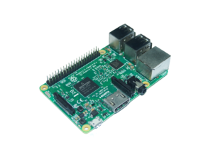
Raspberry Pi has gone through a few iterations and Table 1 shows the list of Raspberry models released over the years and their prices. Of the various models, Raspberry Pi 3 (seeFigure 3) and Raspberry Pi Zero (seeFigure 4) stand out.
Figure 3: The Raspberry Pi 3
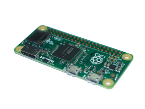
Figure 4: The Raspberry Pi Zero
Raspberry Pi 3 is the third generation of Raspberry Pi and it packs quite a formidable punch in its credit card-sized package. Most notably, in addition to the standard features of the Raspberry Pi (such as four USB 2.0 ports and built-in Ethernet), it has:
A 1.2GHz 64-bit quad-core ARMv8 CPU
802.11n Wireless LAN
Bluetooth 4.1 Low Energy (BLE)
The powerful CPU coupled with Wireless LAN and Bluetooth 4.1 radio makes it an ideal candidate for IoT projects, because multiple sensors can be connected to it simultaneously. In addition, the Raspberry Pi has a 40-pin GPIO (General Purpose I/O) connector for interfacing with external sensors.
The Raspberry Pi Zero is the smallest Raspberry Pi ever made, and although it doesn’t have a processor that’s as powerful as the Pi 3, its small size is especially suited for embedded projects (such as wearables, etc.).
Connecting to a Sensor to Detect Motion
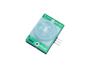
To demonstrate how to use the GPIO to connect to an external sensor, we’ll now use a PIR motion sensor to detect motion. For this, I used the Parallax PIR Motion Sensor (seeFigure 5). The PIR Sensor detects motion by measuring changes in the infrared (heat) levels emitted by surrounding objects of up to three meters.
Figure 5: The Parallax PIR Motion Sensor
The Parallax Motion sensor has three pins (see Figure 6):
GND: The Ground pin. Connect this pin to the GND on the GPIO.
VCC:L The voltage pin. Connect this pin to one of the 5V pins on the GPIO.
OUT: The output pin. Connect this to one of the Input/Output pins on the GPIO.
Figure 6: The layout of the various pins on the PIR Motion Sensor
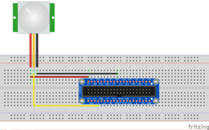
When the PIR Motion sensor detects motion, it outputs a high signal on its output pin. You need to write an application to read the value of this output pin. Figure 7 shows a PIR Motion sensor connected to the T-Cobbler Plus.
Figure 7: A PIR Motion sensor connected to the Raspberry Pi
Acting on the Sensor Data
Now that the PIR Motion sensor is sensing motion, let’s put it to good use. A good application of this project is to install the Raspberry Pi and the motion sensor at home to monitor for unexpected movement. You could mount the sensor near your door to detect movement outside the house when there’s no one at home.